Starting Out – Root Console Commands
These are commands that are usually run outside any console. The switch/router can change consoles based on what you’d like to do, and it’s reflected by the terminal prefix it gives you. If the line you are typing commands into is only a # or a $, you’re in the root console.
Before anything, you should know how to save your work. The configuration file that is loaded on boot is not changed to the configuration file that is running unless explicitly stated
copy running-config startup-configExit the current console and go back
exitReturn to the root console (use this instead of multiple exit commands)
endUndo or delete anything. This can be used for VLANs, static routes, anything. It will do the reverse of whatever the command does.
no <command>Show all VLANs
vlShow the running config file (not the startup one)
show runShow the running config file for a specific interface. These interfaces can be physical, or not. This will work to show you specifics about VLANs, VXLANS, Loopbacks, etc.
show run int <Interface_Name>Show specifics about the interface
show int <Interface_Name>
show int status
Turn on Layer 3 Routing (routing capabilities). This is done on either Layer-3 capable switches or routers.
ip routingShow the routing table. This is helpful for seeing static routes, OSPF routes, connected VLANs, connected subnets from the router’s interfaces, etc.
show ip routeEnter Configuration Console (where most of the following commands will work)
config tWhile in the Configuration Console, you can use this syntax to run root console commands
do <command>Configuration Console Commands
Once some of these commands are run, the terminal will enter additional configuration consoles specific to the task. For example, upon creating a VLAN, the console will change to a configuration console specific to that VLAN, and you’ll see that the terminal prefix changes. Commands to be run inside the additional configuration consoles will be denoted by indentation.
Enter the configuration console specific to any interface
int <Interface_Name>
   shut # shut down the interface
   no shut # start the interface
Create a VLAN
vlan <number>
   name <name>
Assign ports to a VLAN (to be done on the interface that’s directly connected to a client machine)
int <Interface_Name>
   switchport mode access
   switchport access vlan <number>
Assign interface an ip address
int <Interface_Name>
   ip address <address> <subnet>
Assign ports to be used as a trunk
int <Interface_Name>
   switchport mode trunk
   switchport trunk allowed vlan <comma-separated_list_of_VLAN_numbers>
Create a VLAN SVI (to be done on a layer-3 switch or router to give a VLAN an ip gateway)
int vlan <number>
   ip address <address> <subnet mask>
   description <any string here>
Static Routes on a Router/Layer-3 Switch
While in the configuration console, use this syntax to create a static route
ip route <network id of network you want to accept traffic from> <netmask of that network> <ip that's authorized to send it to you>Thus, if you want to receive data for network 192.168.0.0/30 and you’re receiving it from the ip address 192.168.1.1, then it would be
ip route 192.168.0.0 255.255.255.252 192.168.1.1You’ll need to make routes for each subnet you have in the network (even links) that aren’t connected directly to the device you’re configuring
To set a route in a VRF
ip route vrf GLOBAL <ip_address> <subnet> <ip_to_receive_from>Catch all routes can be useful for sending off ANY packet that does not have a specific route defined
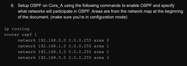
ip route 0.0.0.0 0.0.0.0 <next_hop_address>OSPF on the Router
Example config on high level router:
router ospf 1
area 1 range 192.168.0.0 255.255.255.0
area 2 range 192.168.1.0 255.255.255.0
area 3 range 192.168.2.0 255.255.255.0
network 192.168.0.0 0.0.0.3 area 1
network 192.168.0.4 0.0.0.3 area 2
network 192.168.2.0 0.0.0.3 area 0
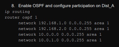
network 192.168.2.8 0.0.0.3 area 3Example config on lower level router (layer-3 switch)
router ospf 1
 network 192.168.0.0 0.0.0.3 area 1
 network 192.168.0.0 0.0.0.255 area 1
 network 192.168.1.4 0.0.0.3 area 1
On the higher level routers, set the individual ips of the links that go to each area. If you have a /30 that goes to area 0,1,2,3 add the subnet that will get you to that area. (the /30 link info)
On the lower-level routers (maybe layer-3 switches), broadcast to the OSPF group that you have a subnet here! Then broadcast the /30 links that get you to here (to your area) as well.
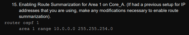
Now that the Router knows which areas exist, use Route Summarization so that the Router knows which traffic should go to which area.
Verify that everything works, then
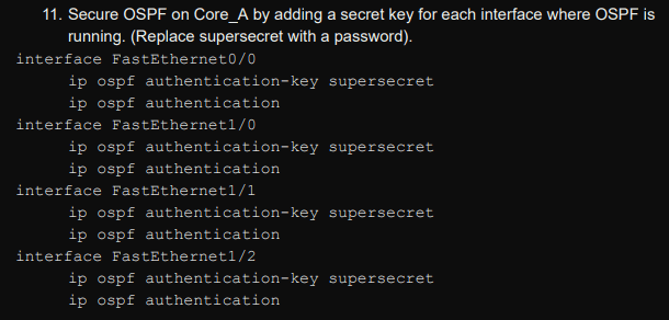
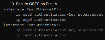
Change the linking interfaces to use a passcode
VRFs on the Router/Switch
Create a VRF
vrf instance <name>
ip routing vrf <name>
Add a VLAN to a VRF
int vlan <number>
   vrf <name>
See routing table of default VRF
show ip routeSee routing table of specific VRF
show ip route vrf <name>Ping another computer within a VRF
ping vrf <name> <ip>VXLANS (extended VLANs)
First, you’ll make an imaginary interface on the router, called a loopback. It’s always going to be running and reachable as long as any interface is up.
int loopback 0
ip address <address> <netmask>
Create a VLAN on each router
vlan <number>Then, you’ll create VXLAN interfaces on each of the routers that needs to send layer 2 data. The udp-port and vni numbers can be whatever you would like as long as they are consistent
int vxlan 1
	vxlan source-interface Loopback0
	vxlan udp-port 4789
   	vxlan vlan <vlan number> vni 1010
   	vxlan flood vtep <ips_to_send_vxlan_data_to_(with_spaces_in_between)>
Set every port on the router/switch that needs to belongs to that VLAN
int <interface_name>
   switchport mode access
   switchport access vlan <number>
Create /30 networks to connect the VLANs and assign those ip addresses to the connecting interfaces
Set static routes between the routers to accept VXLAN data from THEIR loopback addresses
ip route <their_loopback_address> <their_loopback_subnet_mask> <ip_to_receive_that_data_from>If there’s a router with loopback address 2.2.2.2/32 that’s ping-able on 192.168.40.2, then we would use
ip route 2.2.2.2 255.255.255.255 192.168.40.2